Learning system diagramming and computer component functions through literal human-computer modeling
Students develop a human representation of computer components interacting to fulfill their user's request to display a panel of 9 photos of famous people which are stored in non-volatile memory.
Activity overview and links to step photos
This activity involves creating groups of 8-10 students which must each organize themselves to physically model the flow of information and electricity between components as they carry out an instruction from the user to retrieve a specified famous person's picture from a data store on the hard drive.
- Build a class database of famous people, their names and photos, along with a unique 10-digit system identification number and a human-friendly id
- Assign groups and component roles to each group member
- Together, groups create a model of component relationships using white boards and scratch paper
- Digitize the paper model of the system components using a graphic flow chart editor, such as draw.io
- Prepare physical tokens to represent power and data flow between components. Decide on a "communication protocol" between components to accomplish the database lookup task
- Group members physically arrange themselves in an open area to depict component relationships within a standard computer system. The motherboard, for example, is modeled with a blanket
- Implement the human model of component relationships each time the user requests a specified famous person's photo from the database to be displayed on the "screen".
- Observe which components have a "backlog" of work and which ones are remaining idle, waiting for requests to do something (symbolic modeling of a component bottleneck--such as processor speed)
- Debrief on bottlenecks and system functioning and complete the individual module reflection sheets
Learning objectives
This activity is designed to both reinforce the spiraling skill of system diagramming and to instill the high-level view of the function of various computer components. Learning objectives:
- Develop a digital flow chart correctly depicting the flow of electricity and data through the core components of a personal computer
- Devise a physical representation of the interface between one's assigned hardware component and its partner components during the process of a database lookup task
- Describe the concept of a system bottleneck and how the structure of the human model allowed for a real-time viewing of system bottlenecks.
Preparing database of famous people
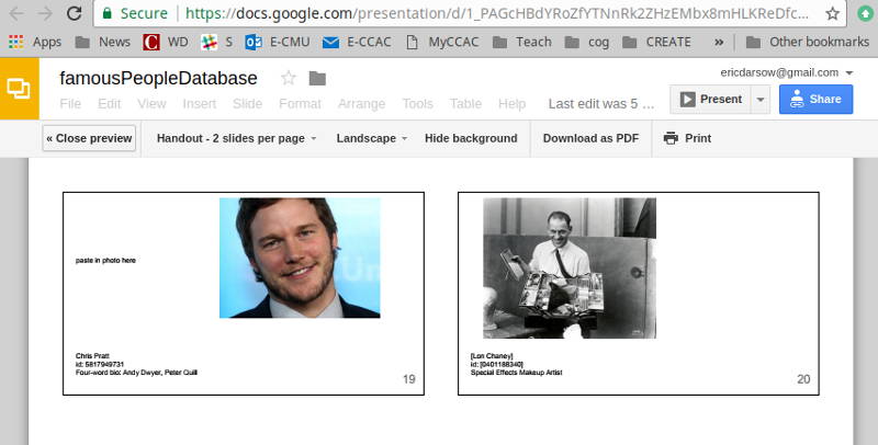
We need something interesting for our computer to do--and so we created a database of famous people and their photos that we want to look up to create a "dream party" guest list. Each student contributed one or more famous people, created a slide with his/her photo, and made a corresponding entry in the database lookup spreadsheet.
Google sheets and google presentation worked extremely well for real-time collaboration during the database creation process. As soon as the slides were inputted and spreadsheet updated, the files were removed from sharing so as to create a static data set to print and distribute hard copy to the components who needed each pair of data columns.
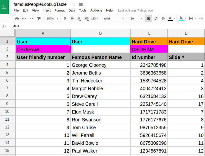
This is the lookup table. You can see that the column headers are shaded with colors to show which columns of this master table are available to which of the three components who interact with this data: the user, the CPU/RAM, and the Hard drive. The ID number in column A is human friendly. Computers, however, look up data based on ID numbers that are "longer" since there's a lot of data that needs to be stored for many applications. This necessitates the CPU and RAM to convert the user-friendly ID number of the requested person into an ID number that the hard drive can use for its lookup.
Assign groups and component roles to each group member
Each person in the group served a specific role as a component in the computer. The following positions were assigned:
- Central Processing Unit (CPU)
- Random Access Memory (RAM)
- Motherboard Communication BUS
- User
- User input device (keyboard)
- Hard Disk Drive
- Power Supply
- Computer monitor/display
- Observer to check for bottlenecks
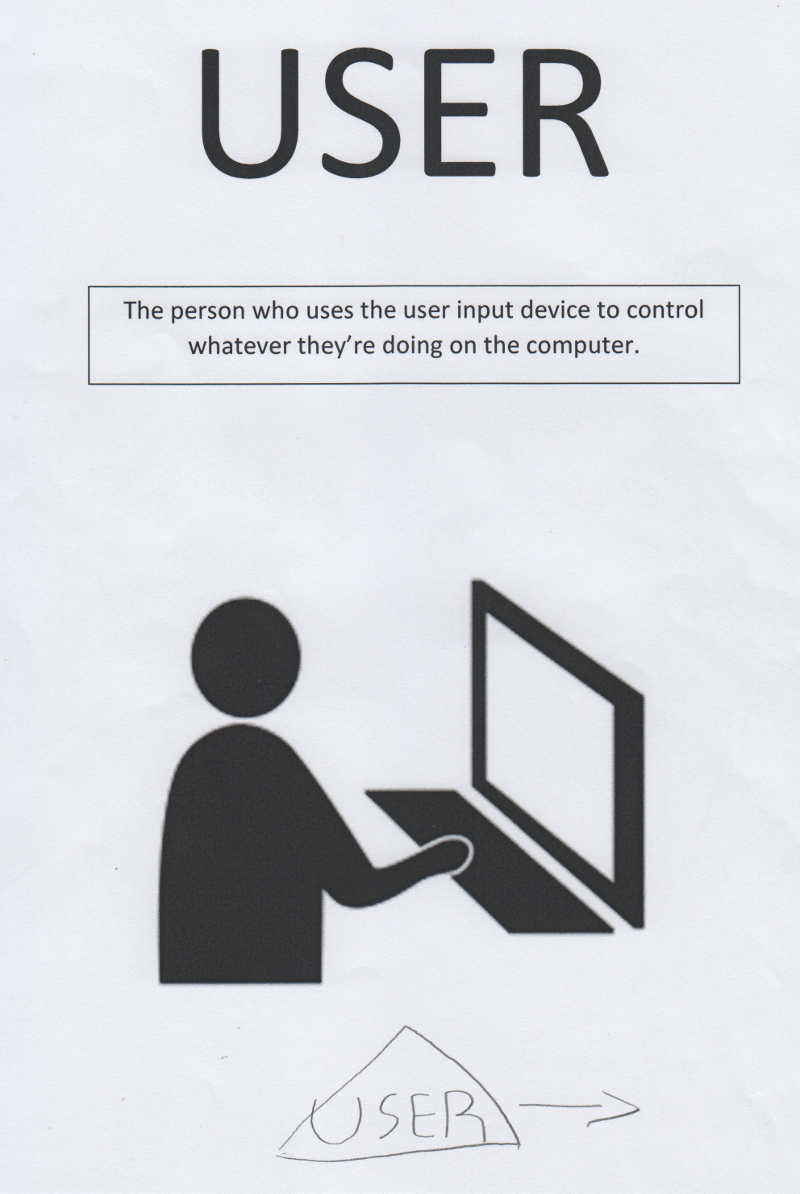
Each person then made a component ID card to place next to them during the simulation. They were asked to draw their component diagram symbol on the bottom of their card. This example has all these components. The author should have added the motherboard BUS as a connecting component to the keyboard for a complete response.
The CIT100 class functioned as one group and used the component model we made together on the class white board to coordinate roles. Note the initials next to components indicating which students will plan for which roles.
Create draft versions of the computer component system relationship
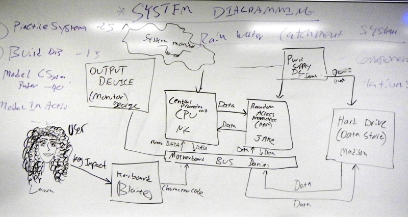
A core skill developed alongside knowledge of computer component function is the process of creating system diagrams showing components and flows between them. The class iterated over this process a few times before arriving at a solid and accurate depiction of relationships. The student's work below shows a first draft diagram, complete with through notes about what components should be included in the model. Embrace the messiness of teh design process!

Digitize the paper model of the computer system
Once students arrived at a solid paper version of the computer component relationship diagram, they used a program like Microsoft Powerpoint or google drive's draw.io to create a digital representation of the diagram. This process facilitated committing to certain relationships by digitally inputting the flow arrows. Groups collaborated on their paper models. Students then made digital versions independently.
Note that this group decided on a shared key for flows and symbols in their diagram. The process of deciding among themselves what each symbol means was an important breakthrough showing ownership of the content.
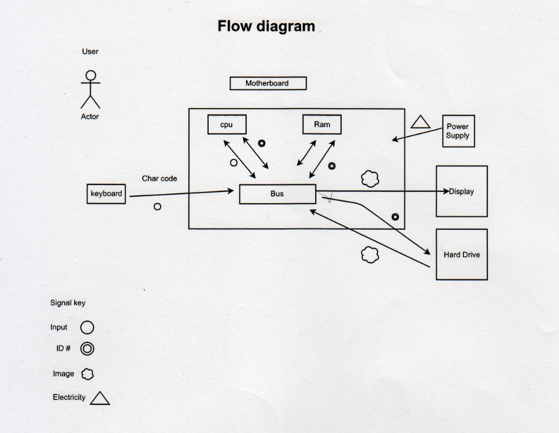
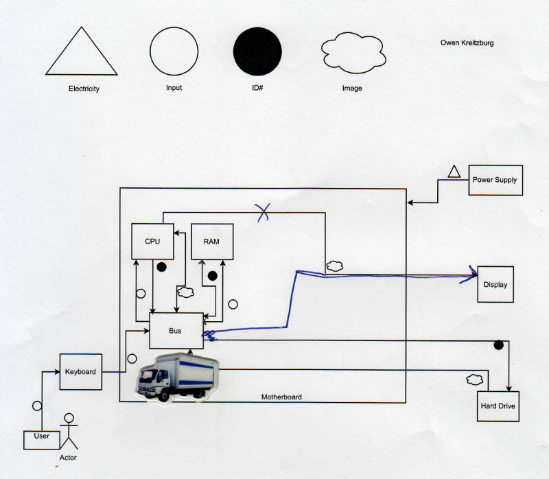
Another group member's digital flow diagram with the shared symbol key included on the diagram's frame.
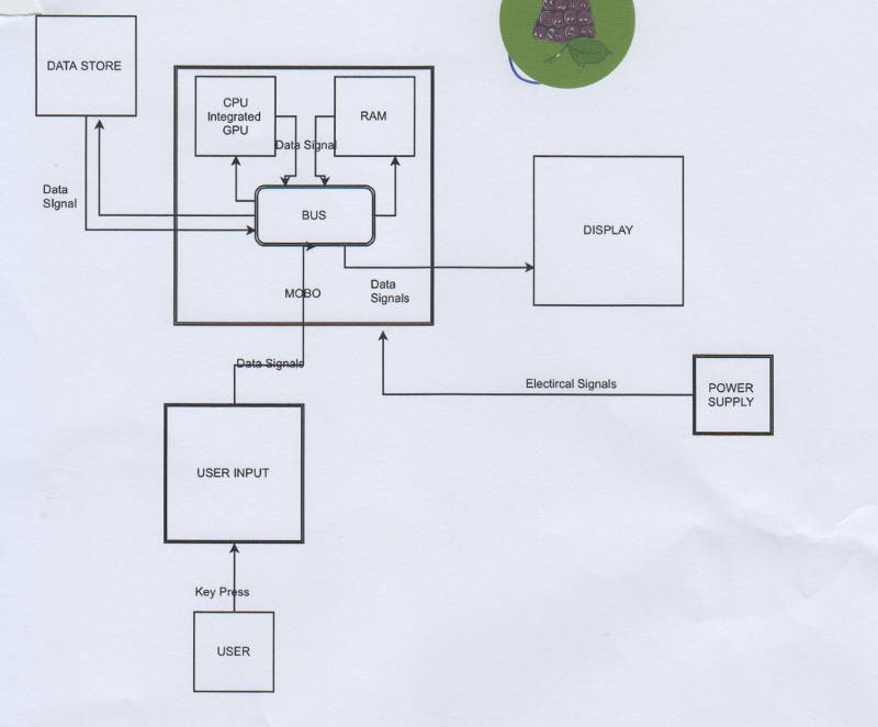
This final digital system diagram was produced by a student in the class's second group which did not generate a shared key. The work, however, shows command of the component relationships.
Creating tokens to symbolize information flow
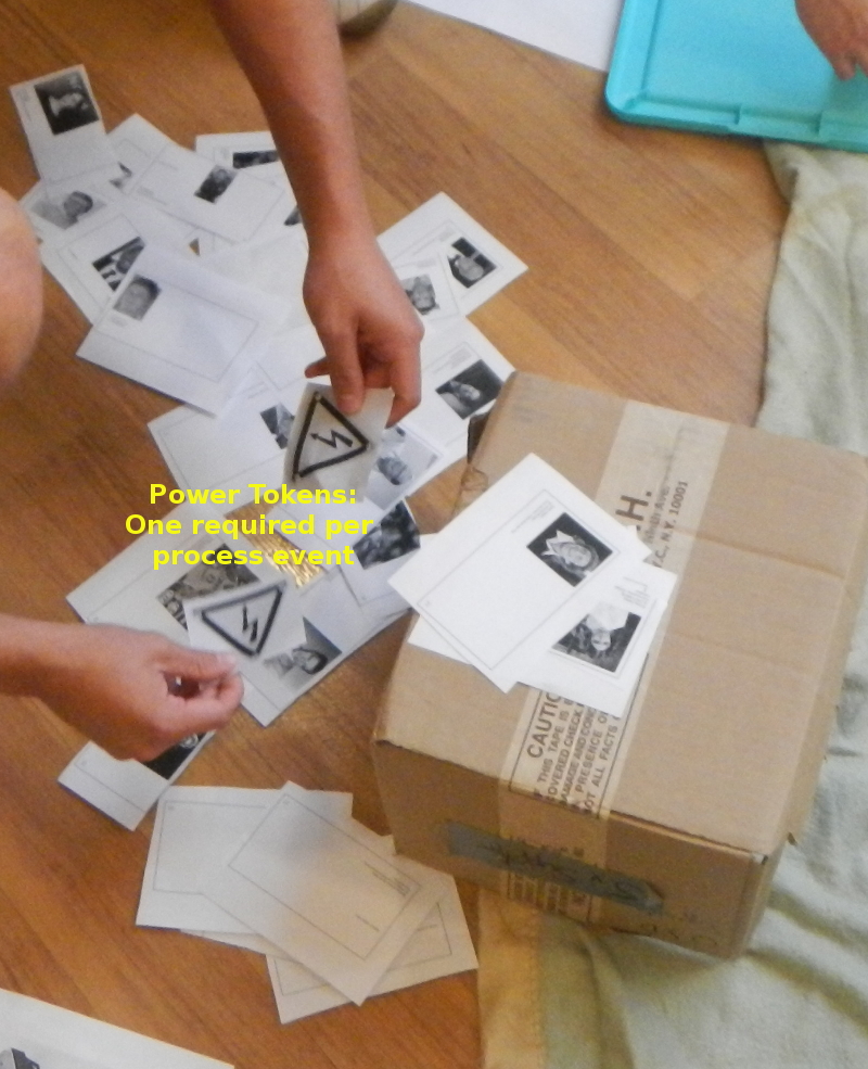
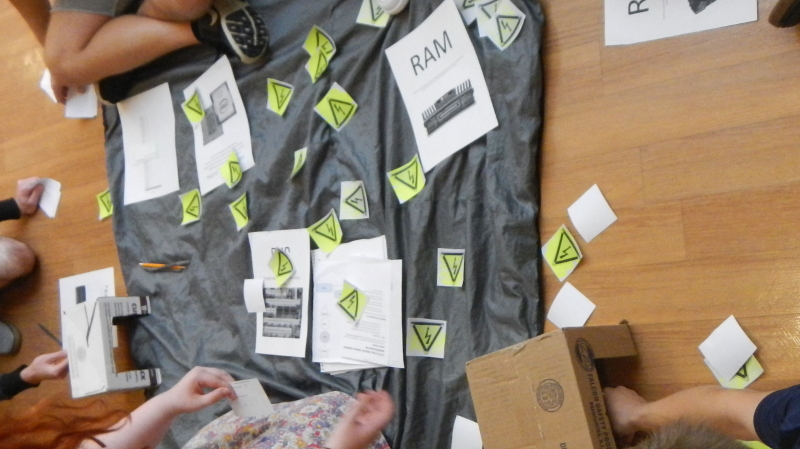
Students internalized a system of tokens that symbolize the flow of electricity and power between computer components. The power supply, for example, distributed little slips with lightning bolts to each component for each process undertaken. The following image shows these power tokens scattered around the motherboard, either queued up for use or discarded for recycling by the power supply.
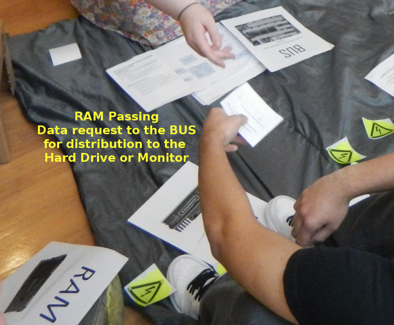
The following image shows data tokens moving from the RAM the motherboard communication BUS.
Physical component arrangement
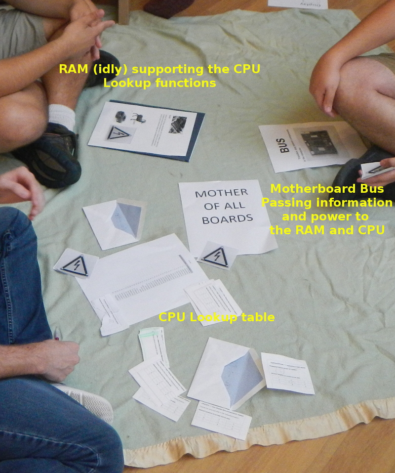
Students were tasked with arranging themselves around the motherboard (blanket) such that data can be passed efficiently between components with minimal moving around. The following image shows the three motherboard components aligned in a nice row to pass information between themselves via the communication BUS. Notice that the BUS and RAM components are idle while the CPU does its processing.
Implementing the human-computer model
The modeling process commences when the user submits a desired celebrity's human-friendly number to the user input device. That data token passes through the BUS into the CPU and RAM, which look up a hard drive address ID number. This internal packet gets routed to the hard drive which uses a table corresponding address ID number to slide numbers to determine the appropriate slide image to return. The data move through the motherboard to the display.
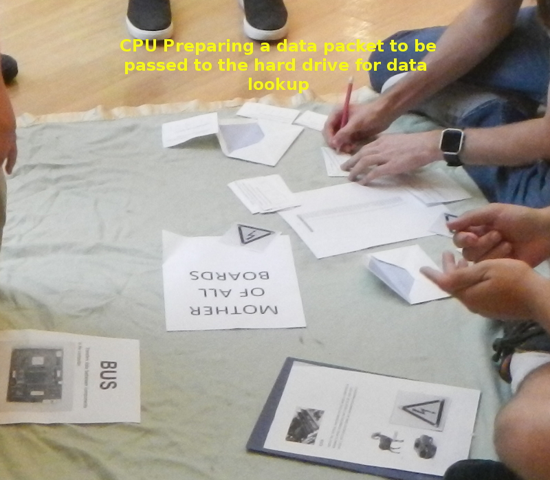
This is an image of a CPU component preparing a data request for the hard drive.
More motherboard staging with plenty of power to go around
Monitoring for bottlenecks
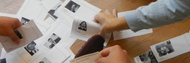
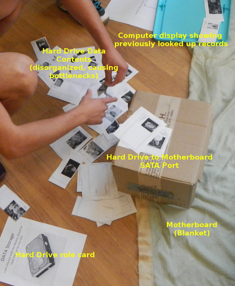
As the students processed each request for a new famous person photo, the student monitors looked for components who were "holding up the show" because their task took much longer than other components'. The photo below illustrates the dangers of a slow hard drive: this hard drive had not devised a working system for looking up picture slides given a hard drive data address. The students readily applied the metaphor of computer components and declared: "We need a hard drive upgrade!"
Debriefing on the exercise
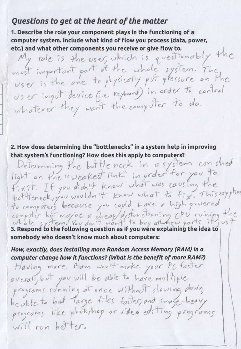
Students completed a half-sheet of core questions about their experience on the project, including a culminating question concerning the role of RAM in the component relationship process. Note that the first work sample shows greater command of the concept of temporary storage and speed, whereas the second work sample illustrates a lack of a solid understanding of the role of RAM in the system. This is noted as a point for re-teaching.
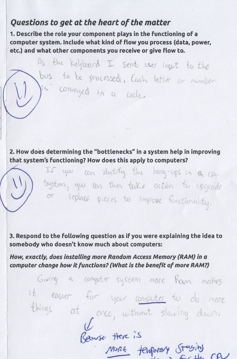
This work sample illustrates a less robust learning outcome:
Reflections and suggestions
- The creation of identity cards arrived rather late in the activity design process. With greater pre-planning, each student's creation of the name card can involve much more in-depth research about how that component works. It should be translated symbolically to the role card.
- Consider leaving about an hour for an 8-group model: run the system once to look for bottlenecks. Then "upgrade" slow components and run the system again.